The grid
1. THE GRID AS AN OPERATING DEVICE
|
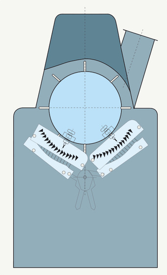
In the final analysis, it is the grid or a grid-like structure under the opening assembly that determines the level of waste and its composition in terms of impurities and good fibers. Grids are segment-shaped devices under the opening assemblies and consist of several (or many) individual polygonal bars or blades (i.e. elements with edges) and together these form a trough. The grid encircles at least 1/4, at most 3/4 and usually 1/3 to 1/2 of the opening assembly.
THE GRID HAS A MAJOR INFLUENCE ON THE CLEANING EFFECT VIA:
|
2. THE ELEMENTS OF THE GRID
|
THE FOLLOWING ELEMENTS CAN BE USED IN THE GRID:
Blades have been used as grid elements for a long time (the mote knife), almost always in combination with triangular section bars. Today, grids are made up of knife blades alone, without other element types. Angle bars are somewhat less robust and can tend to create blockages. |
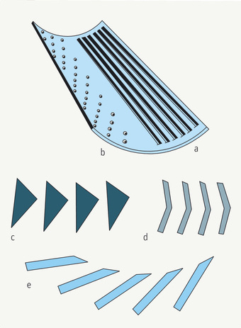
Fig. – The elements of a grid
|
3. WASTE COLLECTING CHAMBERS UNDER THE GRID
Impurities and fibers fall through the grid gaps and accumulate in large quantities in the chamber under the grid. Waste used to be periodically removed manually, but pneumatic removal systems are used today. As far as the cleaning effect is concerned, modern waste chambers are passive elements, without influence on the operation. In older designs they sometimes participated actively, and afforded the possibility of exerting a significant influence on events by permitting some of the transport air for forwarding the tufts (the so-called secondary air) to enter through the waste chamber and the grid. Such systems enabled the interaction of airflow and beating power to be exploited. Heavy particles could drop out, against the airflow through the grid gaps, because of their high ratio of mass to volume. However, fibers were taken up again with the airflow because of their low ratio of mass to volume. Today, this principle cannot be exploited because of the small size of the foreign matter, which would now be carried back along with the fibers. Accordingly, a so-called dead chamber is now used; none of the transport air now passes through the grid gaps.
4. GRID ADJUSTMENT
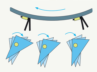
Fig.– Changing the grid bar angle to the beater
|
The grid can be in one, two or three parts. Correspondingly, it can be adjusted only as a unit or in individual sections.
THREE BASIC ADJUSTMENTS ARE POSSIBLE:
|
